SABRE Maps/Online Grid Calibrator
| SABRE Maps In-depth guide | ||
 | ||
| Pictures related to SABRE Maps View gallery (46) | ||
| Quick Links | ||
| Start Here Copyright • Stitching scans • Georeferencing maps in-depth • Creating map tiles | ||
| Related Terms | ||
| SABRE Maps SABRE Maps coverage • Map layer names • Co-ordinate Finder • Sheetfinder • Online Grid Calibrator | ||
The SABRE Maps Online Grid Calibrator is a sub-project of SABRE Maps.
The Online Grid Calibrator allows members of SABRE to easily assist with the georeferencing of maps for use on SABRE Maps. In order to save the data from the Online Grid Calibrator, a SABRE account is required, and the user must be logged in.
The Online Grid Calibrator, in common with the other SABRE Maps sub-projects, is available from the main menu down the left hand side of SABRE Maps.
As well as the assistance offered here, there is a SABRE Maps YouTube playlist offering video guides to assist.
How to start
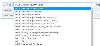
After accessing the Online Grid Calibrator, the first item to complete is to select the Map Type from the options given. This will display all the different map series currently in use within the Grid Calibrator. Some items on this list may not be available - this is where there is currently no map of this type in the georeferencing queue. Selecting the map type will then set all of the relevant settings for that particular sheet type, including the Projection for that map. It will also populate the Map Sheet field with all the maps currently available for that map series.
There are two more advanced map sheet types - ones with "disguised projections" are marked with an asterisk *, and further information on these map types is given in their specific section below. Those that require "Advanced Mode" are marked with a dagger † in the list, and again have their further information in the specific section below.
Choose a map sheet that you'd like to perform the georeferencing on from this list, and the Online Grid Calibrator will then populate all the relevant map data, and load the scanned map image. In this list, the sheet number is the second-to-last item, whilst the revision code is the last item. In this example therefore, OSGB One Inch New Popular Edition sheet 101 revision 1241 is selected.
Note that as the map images themselves are large, it's quite possible to see long image loading times, especially for the larger maps. Please be patient, and the map image will appear.
Finally, all the remains is to click on the relevant locations on the map, starting at the top left, working the way across to the right hand edge, then repeating this across relevant rows until the final row across the bottom of the map sheet to build up the georeferencing data, following the more specific instructions for the map type. In order to assist, the Online Grid Calibrator calculates for you the expected next click position, and shows it in the heading area.
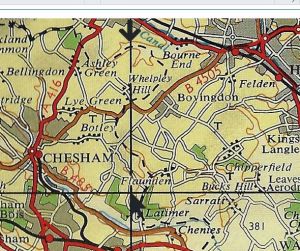
As you click on the map, the last click point will be shown as a black arrow, whilst previously clicked points will be shown with a grey arrow. In addition, downward arrows will be displayed to assist with highlighting each vertical line that is needed to complete the georeferencing - though bear in mind that some map images are slightly skew, so the downwards arrows may end up being slightly offset. Make absolutely sure that you don't accidentally miss any locations as unfortunately that will skew the locations of each click.
When you've finished clicking on all points, an information box should appear to tell you that you've clicked on the map the expected number of times, and offering you the chance to save your work on SABRE's main server, and send a notification to the Maps Team that this map have been georeferenced via the SABRE Forums Private Messaging system, so you can check your PM Outbox or Sent Items if you're unsure it's been sent. If the "last click" box appears, and you've not just clicked on the bottom right-hand corner, then it's also a good indication that something has gone wrong somewhere.
If you press the "Review" button, then the map is redisplayed along with all the points that have been clicked on it. If you're happy with those points, then press the "Save and Send" button.
If you make a mistake at any time, a press of the Undo button will undo the last point clicked on. If you feel that you need to start again from scratch, the Reset button will do precisely that.
How to deal with each standard map and projection type
For OSGB National Grid, OSGB National Yard Grid, and Irish Grid maps
Unless otherwise stated below for one of the more advanced map types, simply start clicking the thicker gridline joins - start at the top left, and work your way along the top, clicking on each thick gridline, with the final point being on the right hand side; then go down to the next thick gridline and repeat. Finally, make sure you repeat the process across the very bottom of the map. Some maps have three thickness of gridlines, with an "extra thick" line showing a grid square boundary. If you're not sure what that means, don't worry - just remember to treat extra thick gridlines as if they're standard thick gridlines.
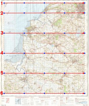
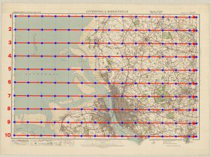
The example image below is of an OSGB One Inch Seventh Series sheet, for which 30 points (represented by the blue dots) are required for a good result. Other map types have a different number, depending on the map size. Note that in the example image, the distance between the top of the map and the first thick horizontal gridline is less than the distance between the following thick horizontal gridlines. This is normal and to be expected.
Follow a pattern across the map as shown by the numbered red arrows in the image below, moving from left to right along each thick horizontal gridline, treating the top and bottom of the map as a thick horizontal gridline. Always "reset" along each thick horizontal gridline, moving back to start from the left hand side for each row as shown in the guide images.
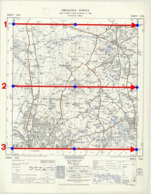
There is a slight exception for OSGB 1:25,000 First Series maps. Due to the small physical size of these maps, they don't actually contain any thick gridlines. To georeference one of these maps, then for most examples nine points are required as shown in the image below; a few maps around coastal areas are a little larger than the standard size, so these will require a few more points.
If you're not sure which ones are the thick gridlines and which ones are thinner, then the "Every" value that appears should give you a pointer. An "Every" value of 10000 will mean that the thick gridlines appear every 10000 units of grid; be that either metres or yards as appropriate to the map. However, remember that maps don't necessarily have their edges to a multiple of the "Every" value, and so don't confuse the meaning of this value and try to do mental calculations as to where to click - always simply click on the thick gridline joins (including the map edges). You can see from the example OSGB One Inch Seventh Series sheet above right that in that example, the top margin isn't at a multiple of the "Every" value and so the places to click are along the top margin, then along the next thick gridline down, not at the value of the top gridline plus the value of "Every".
For Cassini (Delamere) and Bonne maps
Unless otherwise stated below for one of the more advanced map types, for maps that are shown in the Projection field as being one of these more archaic types, simply start clicking every gridline join - start at the top left corner of the map, and work your way along the top, clicking on each gridline, with the final point being on the right hand side; then go down to the next gridline and repeat.
For these map types, the "Every" value displayed simply indicates how far apart each gridline is on the ground in miles, and is again not relevant to how often you click - it's always every gridline for these map types.
Disguised projection maps
Several map types can be thought of as for more experienced users, though this doesn't mean that they're actually difficult to complete!
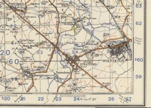
These maps types are mostly what we call disguised projections, where the map is of a different projection to the grid that appears on it. These show up where the gridlines are drawn skew to the map sheet itself, and usually exist so that a newer grid type can be shown on an older map type that was not originally designed for it - for example, the OSGB Scottish Popular sheets that were published post-WW2 to the same projection and sheet layout as their pre-war counterparts, but the old gridlines were removed and replaced with the National Grid. There are a number of examples of this across both British and Irish OS mapping, with the other most common types including the OSI Half Inch where the Irish Grid was later added, and the OSGB One Inch War Edition sheets, where the original gridlines were replaced by the War Office Grid. The extract below from an OSGB One Inch Second War Edition clearly shows the grid as being skew to the map itself.
Disguised projection map types are marked in the Map Type selector with an asterisk * symbol.
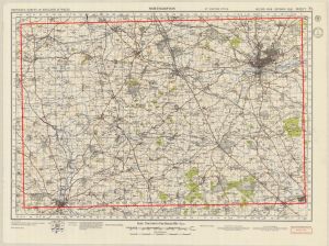
When working with disguised projection maps within the Online Grid Calibrator, the "top" row is taken as the topmost gridline that appears all the way across the entire map, with the three other edges treated similarly - thinking of these gridlines as being the "virtual edges" of the sheet for our purposes may help. The red lines on the below image show the location of these "virtual edges" on an OSGB One Inch Second War Edition map, where the grid is very skew to the underlying map. Clicking on the image will enlarge it. Within the Grid Calibrator, the values of Eastings and Northings are shown for any selected disguised projection map, and these can be used to assist in locating the virtual edges. Note that in the displayed example, northing gridline 59 at the very bottom of the map disappears just short of the true map edge, so it cannot be the bottom virtual edge.
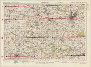
Once the edges have been identified, then the maps can be georeferenced using the standard OSGB National Grid and Irish Grid instructions, i.e. by following a pattern across the map similar to that shown by the numbered red arrows in the image below, moving from left to right along each thick horizontal gridline, treating the virtual edges of the map as if they were the real edges.
Advanced Mode
Some later pre-Grid map sheets, such as some OSGB Popular Edition sheets from the late 1930s had their printed gridsquares moved around to form a prototype "national grid" of grid squares, but without any form of referencing. These are much rarer than the standard sheets, and so they need to be treated differently. These map types are marked in the selector with a dagger symbol, †.
Whilst the majority of map sheets have any narrow gridline columns to the right of the map sheet; and any narrow gridline rows at the bottom, these later maps have them at the left or the top sides to match up with the relevant narrow column or row on the map sheet to that side.
For these map sheets, like standard maps they should be georeferenced always towards the narrow column and row - it's just that the direction of travel may be different.
For example, for a sheet with the narrow column to the left, and the narrow row along the bottom, then instead of moving left to right across the gridline joins, then moving down to the next; move right to left across each row, then down to the next.
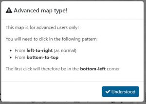
An easy way to tell which directions an Advanced Mode sheet needs to be clicked in is that the "Every" value shown will be negative for the direction(s) to be completed "backwards". The Calibrator will also show a pop-up prompt, informing the user that this map is an advanced sheet and which direction to calibrate the map in (i.e. right-to-left, top-to-bottom). To provide further confirmation, this box also indicates where the first click should be (for example, in the top-right corner).
| Narrow column position | Narrow row position | Starting location | Notes |
|---|---|---|---|
| Right | Bottom | Top left | left to right along top row, complete downwards. |
| Left | Bottom | Top right | Start at the right hand side, move left along the top row. Complete each row downwards in this manner. |
| Right | Top | Bottom left | Start at the left hand side, move left along the bottom row. Complete each row upwards in this manner. |
| Left | Top | Bottom right | Start at the right hand side, move left along the bottom row. Complete each row upwards in this manner. |
| Both sides | Either | None | Use offline calibrator |
| Either | Both sides | None | Use offline calibrator |
Expert Mode
In the standard controls, there is an Expert Mode button. This button toggles the availability of the To, From, Every and Projection fields for manual editing, allowing full control over all aspects of the georeferencing. This should not normally be necessary, but is available for the most advanced use cases or if the given values are incorrect for a specific map sheet.
When using Expert Mode to alter any values, please remember to press Set Calibration before you start clicking on the map, or the new values will not be saved.
If you find that you need to use Expert Mode to correct any corner grid reference values, then please contact the Maps Team for the relevant data to be updated on the master file.
Credits
The SABRE Maps Online Grid Calibrator was created by the SABRE development team, and for some of its routines uses the Co-ordinate converter developed by Ed Fielden for Fielden Maps.
Links
